Solar Panel Shading - Failing Bypass Diodes & Solutions
Introduction
Partially shaded solar panels can result in a significant decline in performance. Panels contain internal bypass diodes that help mitigate the effects of shading. However, in certain conditions, years of regular shading can lead to accelerated diode failure and permanent damage to the solar panel. If left in a damaged state for a long time, it can result in overheated cells, leading to more severe consequences.
In this article, we'll delve into the challenges posed by solar panel shading, explore the potential issues that can occur with failing bypass diodes, and explain how they can be avoided using optimisers, microinverters, or smart shade-aware inverters. We also provide a troubleshooting guide to help detect faulty diodes and explain how you can mitigate the effects of shading.
How shading affects solar panels
Most solar systems use standard string solar inverters, which are connected to groups (strings) of 3 to 14 solar panels. This configuration is used because panels connected in series generate a higher voltage, optimising the efficiency of the solar inverter in converting the DC solar power to AC electricity. In such systems, partial shading over one or more solar panels will result in a noticeable decline in overall system performance. Understanding why shading poses such a problem requires a basic understanding of how solar cells (and bypass diodes) function when shaded. Nevertheless, if any panel within a string encounters significant shading, it can adversely impact the performance of the entire string due to significantly reduced power flow from the shaded panel. This is where bypass diodes can help.
As explained in detail below, bypass diodes can improve performance when areas of shading occur. It is worth noting that solar systems with microinverters do not suffer from the same performance issues when shading is a problem, as these systems allow each panel to operate independently.

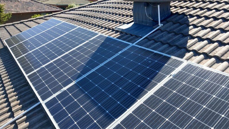
Severe shading across several solar panels resulting in poor performance.
Types of shading
Shading can result from trees, nearby buildings or fixed obstructions like chimneys and evaporative cooling systems, plus natural elements like dust accumulation or bird droppings. When a panel is shaded, it significantly reduces the amount of sunlight reaching solar cells, decreasing energy production. However, shading is generally not uniform, and depending on the amount of shading encountered, there can be very different outcomes.
Shading can be over the entire solar array (across all panels), partial shading across some panels, or shade can happen in a small area over some of the cells on individual panels. While shading across a whole array will severely reduce performance, partial shading on one or more panels may not have much impact on the overall performance. However, partial shading is potentially more damaging if it occurs regularly in the exact location. For example, if a rooftop cooler or chimney is located next to or in front of a solar panel. Regular permanent shading can lead to the formation of hot spots (hot cells) and failure of the bypass diodes, which can significantly decrease solar generation and even develop into a potentially dangerous situation after several years.
Bypass Diodes – The simple solution

When a portion of a solar panel is shaded, the shaded cells will produce less power (low current). Meanwhile, the unshaded cells will be producing full power (high-current), and a reverse current situation will occur where the current can flow back into the shaded cells, resulting in overheating of the cell. This is where bypass diodes save the day. Diodes are small, cheap, long-lasting devices that only allow electrical current to flow in one direction. These are available in many varieties and are used in all kinds of power electronic devices.
How bypass diodes work in a solar panel
Most modern solar panels contain bypass diodes to provide an alternate current path when a cell or multiple cells become shaded or faulty. The diodes are generally located within the junction box on the rear side of the PV module. Diodes are relatively simple devices that allow current to only flow in one direction, enabling current to bypass the solar panel under certain conditions. They do this by opening or closing depending on the voltage bias direction.
Most solar panels are divided into three groups of cells connected in series, with each group containing a bypass diode. In older 60-cell panels, the panel is divided into three groups of 20 cells, while in modern split-cell panels, the panel is divided into six groups of either 20 or 24 cells, with two groups associated with one bypass diode. If it were cost-effective, there would be one bypass diode for each cell, but this is complex and expensive to integrate, so most manufacturers use one diode for a group of series cells.

A basic solar panel diagram showing the 3 bypass diodes (one for each group of 20 cells). Shading some of the cells causes a reverse current and forces the diode to open which bypasses the shaded part of the panel.
Technical Explanation - Voltage Activation of Bypass Diodes
The bypass diode activates when one or more cells in the group are shaded or underperforming, resulting in a voltage and current drop. Solar cells in a typical panel generate about 0.5 to 0.6 volts under standard conditions. For a group of 20 cells, the total output would be around 12 volts. Meanwhile, a typical bypass diode has an activation voltage of approximately 0.7 volts, known as the forward voltage threshold. If a section of cells is shaded, the voltage and current can drop significantly. When the forward voltage across the diode (i.e., the voltage from the unshaded cells in the rest of the string is higher than the voltage of the shaded section) exceeds about 0.7 volts, the diode becomes forward-biased and allows current to flow. This effectively bypasses the shaded cells, allowing the rest of the panel and string to operate at a higher efficiency.
The current that flows through the bypass diode is essentially the same as the current generated by the unshaded sections of the panel. When the diode is active, it simply allows the current to bypass the shaded section to maintain consistent flow through the circuit.
How shading can lead to bypass diode failure
When a bypass diode is activated due to severely shaded cells, some energy passing through the diode is dissipated as heat. Continuous operation of bypass diodes under shaded conditions can eventually lead to overheating and potential failure. Diodes are more prone to failure over time due to factors such as high temperatures, humidity, and electrical stress during continuous operation—learn more about bypass diode failure modes. The different types of shading (light or heavy shading) have a big influence over whether or not the diodes will be activated and what amount of stress they will be under. Light shading from nearby trees is less problematic than heavy shading from close, fixed rooftop-mounted objects.
Light shading
If your system suffers from regular shading over a large area due to a nearby tree, the panels will encounter what could be judged as medium or light shading, especially if the tree loses its leaves in winter. In this instance, the bypass diodes may not be forced to activate due to the large shaded area over numerous panels. Significant shading also results in lower string voltage and current, resulting in less heating if the diodes are activated. In this situation, the diodes may not need to function and could work without issues for a long time.
Additionally, if the shading occurs early in the morning or later in the afternoon, the amount of sunlight (solar irradiance) will be much lower, reducing the voltage and current in the string. This, in turn, results in far less thermal stress on bypass diodes if they are active due to shade.
Heavy shading
On the other hand, it has been found that rigid or fixed shading over a small area on panels installed next to roof vents and chimneys can cause diodes to be active for long periods of time, leading to premature failure. This is especially true if the shading occurs in the middle of the day when the solar irradiance is at its peak.
Failed bypass diodes can allow a reverse current to heat up the shaded cells, resulting in burn marks from extreme hot spots. This accelerated failure can occur for two reasons: the overall panel and junction box temperature is much higher when most of the panel is exposed to sunlight, and voltage and current flowing through the panels and diode are higher when only a small portion of a panel is shaded during the middle part of the day. These two factors result in increased thermal stress on the diode, leading to failure.
What happens when bypass diodes fail?
When a diode fails, it can happen in two ways. It may become permanently open (open-circuit) or permanently closed (short-circuit). In my personal experience, and what other installers have reported, they tend to fail permanently closed (permanently bypassed), resulting in reduced power at all times, even without shading. However, bypass diodes that fail in an open position can have far greater consequences, as the reverse current cannot be blocked when cells are shaded. This can lead to overheating of the cell and a thermal runaway, resulting in internal arcing and burning of the rear polymer back sheet. If left for a long time, it can even lead to fire.
The whole idea of bypass diodes on panels is that they are rarely used. Daily activation due to hard shade from nearby objects, especially during hot summer weather, eventually leads to diode failure.

Can bypass diodes be fixed or upgraded?

An older type solar panel junction box showing the three serviceable bypass diodes in the middle.
Solar panels contain one or more junction boxes mounted on the rear side, which house the bypass diodes and provide a secure connection point for the interconnection cables. Until around 2017, most solar panels were of the standard 60-cell format and had a single junction box with a removable lid, allowing users to inspect and even replace the diodes. Unfortunately, this design sometimes led to water ingress, and over the years, the junction boxes evolved into smaller enclosures filled with potting compound (polyurethane), which are not serviceable. The diodes used in solar panels are Schottky diodes, which are common semiconductor-metal based diodes. These low-cost diodes are typically rated at 30A or higher and can withstand up to 1000V.
Non-serviceable junction boxes and diodes
Unfortunately, replacing diodes in most modern solar panels is almost impossible. By almost impossible, I personally managed to replace several blown bypass diodes around two years ago, but not without great difficulty. The process involved carefully scrapping out the potting material from within the junction box, cutting out the blown diode, soldering in a new one, and finally refilling the junction box with a fire-resistant filler. Replacing three diodes took several hours, but it was successful, and the panels are still in operation today. Unfortunately, if the panel fails for another reason, it will not be covered by warranty due to my modifications.

Junction boxes in modern solar panels are not designed to be serviceable, so replacing a faulty diode is extremely difficult as they are encased in a potting compound that is almost impossible to remove.
Potential Diode Improvements
Diode lifespan could be increased by integrating small aluminium heat sinks to dissipate heat, but a problem with this is that any exposed metal could become dangerous and cause an electric shock or short-circuit. Another improvement is to use durable, water-resistant junction boxes that cover a heatsink and provide airflow. However, manufacturers are in a constant cost battle, and considering the already low cost of solar panels, the extra costs mean that the numerous competitors will get an advantage. Unless, of course, it is marketed as a premium feature. Fortunately, some manufacturers are using higher grade TO-220 package Schottky diodes, which typically have a longer lifespan. We can only hope this problem is addressed at some stage with advancements in diode or panel designs. In the meantime, it is clear that panels should always be mounted to avoid direct shading, especially from roof-mounted obstacles.
Failed Bypass Diode Troubleshooting Guide
As explained below, directly testing whether a diode has failed can be easy on older panels, which allow access to the diodes, but the same task is very difficult on most modern panels. Fortunately, you can use direct and indirect methods to help diagnose a problem. However, before you can test the panel or diode, you must locate the faulty panel, which could be anywhere in a string of up to 15 panels. If local heavy shading is obvious on one or more panels, it will likely be the culprit and the best place to start. However, if the faulty panel location is not obvious, some tests will need to be conducted to isolate the problem panel or panels. We recommend you consult a solar professional, as high DC voltages can be extremely dangerous.
How to locate a potential faulty panel and diode
The first part of troubleshooting a potentially faulty diode in a solar array is to find the faulty panel. Always turn off the inverter and the DC isolator before doing any testing. Once the solar system is deactivated, it can be relatively straightforward to locate a panel with a faulty diode that is permanently open (open-circuit), as it will result in a lower panel voltage. As explained earlier, most solar panels are divided into three sections with a diode associated with each group of cells. If one diode has failed, the voltage will typically be 10 to 15 volts lower than expected, depending on the open-circuit voltage of the panel.

Testing the panel open circuit voltage is an easy way to check if a panel has a blown (short-circuit) diode
For example, if we have a string of nine unshaded panels with the open-circuit voltage (Voc) of each panel being 42 volts. In this case, a panel with a faulty diode will only deliver around 26 to 28 volts when measured under normal sunlight. To locate the faulty panel, the string could be divided into three groups of 3 panels. The groups delivering roughly 120 to 126 volts are good, while those measuring 105 to 112V may contain a faulty panel and diode. The panels in the faulty group can then be isolated and tested individually to find the faulty panel. However, if all groups read the same voltage, then the diodes will either be ok or the diode may have failed in the closed-circuit condition.
If you have located a suspected faulty panel, below are three methods to help detect a damaged bypass diode:
Visual Inspection and Thermal Imaging
Visual Inspection: On older panels with a serviceable junction box, you can remove the cover and visually inspect the diode for signs of damage, such as cracking, discolouration, or melting.
Thermal Imaging: If the bypass diodes are not accessible, using a thermal imaging camera can help detect failed diodes. A solar panel with a faulty diode during normal operation may exhibit abnormally hot cells compared to functioning ones. This method is particularly useful for identifying issues in real-time and can be conducted under normal operating conditions without removing the panel.
Electrical Testing with a Multimeter
Diodes in panels with a serviceable junction box can be tested by disconnecting the solar panel from the array and using a multimeter to test the bypass diode directly. A working diode should show low resistance in one direction (forward-biased) and high resistance in the opposite direction (reverse-biased). If the diode shows low resistance in both directions or high resistance in both directions, it is faulty.
Performance Monitoring
Monitoring the solar array's performance can indirectly indicate the failure of one or more bypass diodes. If a particular string is underperforming, producing less power than expected or fluctuating power output, this can be a sign that a diode has failed. This underperformance is typically notable in unshaded conditions where a functioning bypass diode should not be active. Data from performance monitoring systems can be analyzed to detect these anomalies, which could suggest a diode problem, among other potential issues.
Each of these three methods has advantages and should be chosen based on the tools available and the type of solar installation. However, working on solar arrays should only be done by experienced solar professionals as you can be exposed to dangerous voltages. Additionally, working at heights on rooftops can be very dangerous.
Three ways to reduce the effects of shading
The first step is to check that no trees or branches have grown significantly, causing shading on one or more panels. Note this may not be obvious during the middle of the day when the sun is much higher in the sky. More importantly, pay particular attention to shadows cast by fixed rooftop obstacles such as chimneys in the middle of the day. Depending on your latitude, the sun's path can vary dramatically from summer to winter, so ensure you check throughout the year. Shading during the middle of the day in summer can result in much more severe problems due to the higher temperatures, which can accelerate degradation and diode failure.

A power optimiser mounted on the rear side of a solar panel helps avoid diode failure if the panel is partially shaded.
Use Power Optimisers
If regular shading on a few panels is a problem, it can be overcome by adding power optimisers to the affected panels, such as those from Tigo or Huawei. Power optimisers are small add-on devices attached directly to each solar panel, enabling each panel to operate independently. If significant shading occurs across most of the panel, the optimiser will bypass the entire panel, meaning the bypass diodes will not need to be activated as the panel is effectively isolated or bypassed from the string. SolarEdge offers another unique power optimisation solution. SolarEdge systems use power optimisers on every panel in the string and can control and optimise the system to perform at its optimum under most shaded conditions.
Relocate Solar Panels
An obvious solution to some shading issues is to relocate the shaded panel or panels to another location if an unshaded roof area is available. If the panel cannot be relocated, removing a severely shaded panel mounted close to a rooftop-mounted obstacle or wall might be a worthwhile precaution to prevent a diode failure leading to a potential catastrophic failure in the future. Either way, the shaded panel will not perform well, so removing it completely could be a smarter and safer option. During the design stage of a rooftop solar array, if hard local shading cannot be avoided, power optimisers should be added to the string. Alternatively, microinverters should be used instead of string inverters.
Select an Inverter with Shade Optimisation
Several modern solar inverters, including most inverters from Fronius, SMA, Goodwe, and GE, feature advanced Maximum Power Point Tracking (MPPT) technology that can significantly reduce the effects of shading. This is done using a sophisticated shade-aware algorithm that can effectively “search” the string voltage to find the optimal operating point where the panels will produce the maximum possible power.
Shading and String Voltage: Throughout the day, the string voltage constantly varies due to changes in temperature, solar irradiance, and shading; this is where standard inverters can struggle to find the true maximum power point under these constantly changing conditions. When partial shading occurs, the power-voltage (P-V) curve of the solar panel becomes more complex, often exhibiting multiple peaks (local maxima), making it harder for the inverter tracker (MPPT) to find the optimum voltage.

Shaded Vs Unshaded solar power curve - Inverters with shade detection algorithms adjust the operating voltage to maintain the maximum power point
Shade Detection: Some inverters have shade detection algorithms that dynamically adjust the operation of the MPPT (maximum power point tracker) due to voltage fluctuations from shading. These advanced, shade-aware inverters can scan the P-V curve to identify the new (global) maximum power point rather than settling on a less optimal local maximum. By operating at a slightly different point on the P-V curve, the inverter can avoid the performance drop when shaded cells restrict the current flow through a string. By dynamically adjusting the string voltage, the inverter can generate the maximum power under all conditions.
Summary - Avoid shading wherever possible.
While power optimisers, microinverters and shade-aware inverters can all help mitigate the negative effects of shading, the best way to prolong panel life and prevent diode failure is to avoid shading in the first place. Of course, this is not always possible with trees and other nearby buildings. However, it is relatively easy to avoid shading from fixed rooftop obstacles by not installing panels nearby or by relocating rooftop-mounted obstacles like antennae and satellite receivers. As with most things, prevention is the best medicine.